For most people, building any electronic circuit would be convince by buying or making a board or a PCB. I used to be like that until I experience that doing point-to-point circuit is more fun. First, I free to use any case I want that not limited to the board design and second, the layout could be limitless. Including this B1 buffer pre-amp is the most simple circuit design by Nelson Pass. The sound produce is neutral yet doesn't need much components in it.

Learning from my previous project here, gainclone amplifier will work best when combining with the buffer. This B1 buffer will be combine in the same case with my car Gainclone amplifier here. The building process would be similar when I building this B1 for home audio. I started this project by using an universal board. I measure the length to be fit on the case and the B1 components as well.

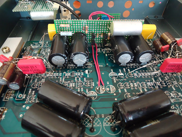
The layout would be like this, four electrolytic capacitor rated each 6800uF in parallel. They are divide in 2 section: primary and secondary caps. In the middle of them would be the 4 pieces 2SK170. I am using BL grade in this project.


I put the 10k ohm resistor along with diode and connect them to the secondary capacitors.


This big capacitor is 1uF for the power supply section. I am using MBM Russian paper in oil capacitor.


Next is put 10k ohm bleeder resistor.


Then the 1 mega ohm is connect between caps to the gate of the FET.

I make a jumper between the 1 mega ohm across the supply rail to the drain of each FET.

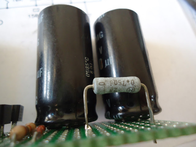
For the filter resistor, I am using 2 watt 0.75 ohm from Panasonic. The value is lower than suggested layout but it is still okay.
The main board of B1 is now done. I will attach this board on the same board with the power amplifier.


The input cable from previous Gainclone car amplifier project is now removed. This lead will connect to the output of the B1 directly.

I put 120k ohm across the input and the ground. I lower the value to minimized any hum occurs at the output of B1.

Then the resistor is now connected. It is 1k ohm as suggested from the schematic.

Before continue to the B1 board, I am now making the power supply section. It is from LM317.

It is simple schematic that I follow directly from the datasheet. This voltage regulator is better than 78xx family and it is fully adjustable.

See how I mount this voltage regulator. The input supply is taken directly to the positive and ground of main power supply.

I am checking the regulator and adjust the voltage before continue to the next step.

The next step is connecting the input section. I am using separate pcb for input capacitor and a potentiometer. I using 1uF MBM and Alps stereo potentiometer.

The resistors is from Dale and connected between the caps and the potentiometer as per schematic layout.

I connect the RCA input socket to the potentiometer board.

This cable will be connect to the B1 board.

I connect the cable to the gate of the FET.

The output is also connected from the middle of the FET's directly to the 10uF caps. I am using cheap MKP capacitors here.

Connect the end of the 10uF MKP capacitors to the previous resistors above. That would be the output of this B1. I also connect the power supply regulator to the B1 board.
Hot glue is using here for keep the board on-board:)

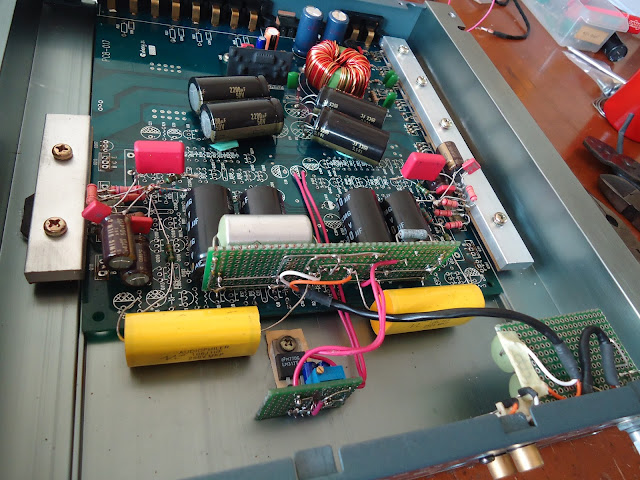
It is now done. Fully integrated gainclone amplifier along with B1 buffer pre-amp.

Testing the amplifier and it is working very fine. But only one problem occurs. When this amplifier is powering on, there is a pop noise from the B1 buffer. Actually it is a common behavior from buffer or pre-amp when they are turning on. That is why in home audio you should turn on from the source to the power amplifier and turn off from the power amplifier to the source. This procedure should eliminate that noise.
In this project, the power supply section for B1 is using the same power supply for the amplifier itself. That is why the amplifier and the buffer will be power-on at the same time.

To solve this noise issue, I using a relay circuit at the speakers output. t will delaying few second before the relay engage after turn on the unit.

Now the amp is completely done and noise free.

Disclaimer: Any statement and photos in this article are not allowed to copy or publish without written permission from the writer. Any injury or loss from following tips in this article is not under writer responsibility.
Learning from my previous project here, gainclone amplifier will work best when combining with the buffer. This B1 buffer will be combine in the same case with my car Gainclone amplifier here. The building process would be similar when I building this B1 for home audio. I started this project by using an universal board. I measure the length to be fit on the case and the B1 components as well.
The layout would be like this, four electrolytic capacitor rated each 6800uF in parallel. They are divide in 2 section: primary and secondary caps. In the middle of them would be the 4 pieces 2SK170. I am using BL grade in this project.
I put the 10k ohm resistor along with diode and connect them to the secondary capacitors.
This big capacitor is 1uF for the power supply section. I am using MBM Russian paper in oil capacitor.
Next is put 10k ohm bleeder resistor.
Then the 1 mega ohm is connect between caps to the gate of the FET.
I make a jumper between the 1 mega ohm across the supply rail to the drain of each FET.
For the filter resistor, I am using 2 watt 0.75 ohm from Panasonic. The value is lower than suggested layout but it is still okay.
The main board of B1 is now done. I will attach this board on the same board with the power amplifier.
The input cable from previous Gainclone car amplifier project is now removed. This lead will connect to the output of the B1 directly.
I put 120k ohm across the input and the ground. I lower the value to minimized any hum occurs at the output of B1.
Then the resistor is now connected. It is 1k ohm as suggested from the schematic.
Before continue to the B1 board, I am now making the power supply section. It is from LM317.
It is simple schematic that I follow directly from the datasheet. This voltage regulator is better than 78xx family and it is fully adjustable.
See how I mount this voltage regulator. The input supply is taken directly to the positive and ground of main power supply.
I am checking the regulator and adjust the voltage before continue to the next step.
The next step is connecting the input section. I am using separate pcb for input capacitor and a potentiometer. I using 1uF MBM and Alps stereo potentiometer.
The resistors is from Dale and connected between the caps and the potentiometer as per schematic layout.
I connect the RCA input socket to the potentiometer board.
This cable will be connect to the B1 board.
I connect the cable to the gate of the FET.
The output is also connected from the middle of the FET's directly to the 10uF caps. I am using cheap MKP capacitors here.
Connect the end of the 10uF MKP capacitors to the previous resistors above. That would be the output of this B1. I also connect the power supply regulator to the B1 board.
Hot glue is using here for keep the board on-board:)
It is now done. Fully integrated gainclone amplifier along with B1 buffer pre-amp.
Testing the amplifier and it is working very fine. But only one problem occurs. When this amplifier is powering on, there is a pop noise from the B1 buffer. Actually it is a common behavior from buffer or pre-amp when they are turning on. That is why in home audio you should turn on from the source to the power amplifier and turn off from the power amplifier to the source. This procedure should eliminate that noise.
In this project, the power supply section for B1 is using the same power supply for the amplifier itself. That is why the amplifier and the buffer will be power-on at the same time.
To solve this noise issue, I using a relay circuit at the speakers output. t will delaying few second before the relay engage after turn on the unit.
Now the amp is completely done and noise free.
This is the simple car amplifier with B1 buffer featuring the beauty of point-to-point wiring and the natural sound.
Disclaimer: Any statement and photos in this article are not allowed to copy or publish without written permission from the writer. Any injury or loss from following tips in this article is not under writer responsibility.
Comments
Post a Comment