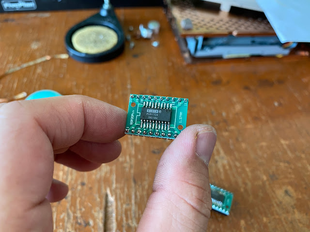
I continue my post about the building process of this ultimate USB DAC using PCM1704 and vacuum tube output.
I choose this PCM1704 as part of this ultimate DAC project is because this PCM1704 is the latest R2R multibit DAC and discontinued before year of 2000. This PCM1704 is the only off-shelf IC that capable of 24 bit and 96 kHz sampling rate.
For the analog section will consist of a vacuum tube per channel. It is 6DJ8 tube that very popular and easy to find the upgrade replacement.
So let's continue.
As usual, I starting with a plain universal board and here is the construction of the DAC section.
The USB receiver is XMOS U204 with Altera Max-2 capable to translate from USB to I2S. This receiver module is sophisticated because it has 3 independent crystal for clocking. It also DSD output capable. You can check my experiment with the DSD output here, although for this project, the DSD is not use and the digital source should convert any DSD file to PCM first.
The I2S output from the USB receiver board are translate by the shift register using 74HCT164. This circuit are shift the signal and separate between right and left channel to the DAC IC in the non-oversampling mode. I use the schematic based on here.
But when it implement for the vacuum tube at the analog section, it stop on the current output at pin 13 on each PCM1704 DAC IC's.
The power supply regulator is including in this DAC board.
As usual, I using 317 and 337 adjustable regulator for this DAC. This is quite simple layout since it only using +5 volt and - 5 volt.
The DAC board can be stop here. But I adding another 3,3 volt regulator for supply the USB receiver board.
This XMOS U204 and Altera Max-2 is BUS voltage capable, means it can be powering ON using the USB power input along with the data transfer from the host. But it only works for PC or laptop, not for connecting to Android smartphone with UAPP application.
The solution is to add external power supply for this USB module, then the UAPP can detect this USB receiver as an external DAC.
As you can see this DAC section is completely done.
The IV conversion is construct using only 220 ohm resistor from pin 13 on each PCM1704 DAC IC to the ground.
The LPF is L-C-L-C configuration using each L is 120 mH and each C is 22 nF.
After this DAC section complete, I can go to the analog section now.
The analog section is using a vacuum tube for each channel.
The configuration for each vacuum tube is SRPP which amplify the small signal output from the passive IV and LPF section before.
This method is very simple and only few connection with the socket and few resistors and capacitors, this analog section is completely finished.
And the last step is finding the original PCM1704 DAC IC which I taken out from the working car head unit Clarion HX-D1.
That is all for this DAC and analog section. Quite simple in my opinion.
I will continue the next part is connecting each board together inside the chassis.
Disclaimer: Any statement and photos in this article are not allowed to copy or publish without written permission from the writer. Any injury or loss from following tips in this article is not under writer responsibility.


No comments:
Post a Comment