A short brief about my Ultimate DAC built since last year are all having the same principles. The first things, they are optimized in the power supply section, using the best components possible and the better layout. Then the second things, they are theoretically the best to implemented.
For sure, all of my DAC built are never the same. I keep experimenting different kind of digital receiver, DAC IC and analog section variation to aim the best sound from the multibit vintage DAC.
With all of my previous DAC built are using the solid-state output, means they are using op-amps as the IV conversion, LPF and buffer output, but I have one dream to make a DAC using the vacuum tubes output.
And I think this is the right time to make it happen.

In this part 1 is all about the power supply section.
Early disclaimer, vacuum tube is the vintage transistor that require high voltage to operate them. This project is not for beginner and please do not try to attempt anything in this post without any electronic experienced.
This project has been long delay due to my routine. The other reason is finding the good components, especially for the power transformer is very hard.
In all of my built, I always using high quality and well known source for collecting the parts. Just like the high voltage power transformer that I am using here is dismantled from Sonic Frontier SFD-2 DAC.
This is Hammond power transformer with the secondary output is 150 volt 50mA and 10 volt 3 ampere only to powering the vacuum tubes analog section that will be discuss later.

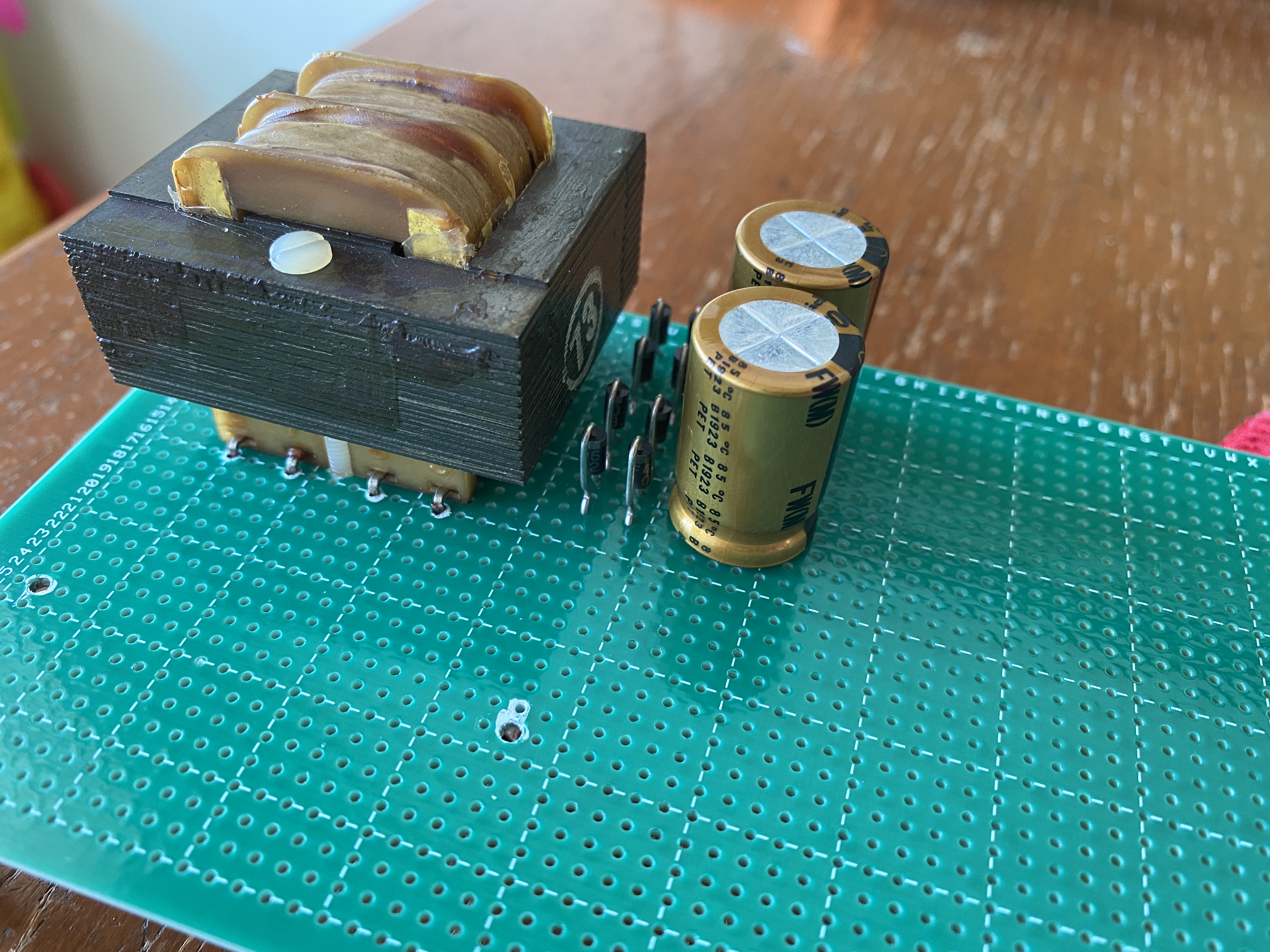
Then I need to put this transformer on the single layer FR-4 universal PCB and start to populating the basic power supply components such as diodes and capacitors.


I am using C-R-C configuration for the first DC filter regulation. It is using a 100 ohm resistor in series with 2K2 ohm to the ground for the safety snubber resistor. Those high voltage capacitors are high quality Nichicon VZ.


I measure the DC out from this high voltage power supply is around 220 volt. And this is the first PCB for the power supply section.
Now I am going to the second section of the power supply.
The second section of the power supply will be consist of the low voltage transformer for the DAC section and the high voltage regulator circuit along with the vacuum tubes heater regulator circuit.


I am starting with this small - low voltage power transformer first.
This power transformer secondary output is dual 10 volt with total power output is around 10VA. It is more than enough to powering the DAC section.

This simple DAC power supply is now done. This will connect to the DAC section later on.
The next things I need to do is populating the voltage regulator's components for vacuum tubes heater
The IC for this regulator are using 7806.


I am using high quality 7806 regulator from Motorola. Each regulator will supply for each vacuum tubes heater at the analog section.
Those regulator IC's need to attach to the large heatsink. They will running very hot with each of them will draw at least 300 mA of current.
I have finished with this tubes heater regulator, then I continue to the high voltage power supply for the vacuum tubes section.

The high voltage power supply regulator circuit using IRF830 Mosfet transistor. It require one transistor per vacuum tubes. The circuit is actually a basic power supply with 180 volt Zener diodes, so the output voltage will stable as per Zener specification.
The difference in this circuit is I using a delay voltage incremental using high resistance and capacitors, so once the unit is powering ON, then the voltage output will swing gradually from 0 to 180 volt in about 30 second. This circuit behavior is just like using a vacuum tube rectifier.


To make sure every connection are correct, then I checked the circuit by powering it ON.
This power supply section are all now finished.


The next post will continue to the DAC and vacuum tube analog section.
Stay tuned.
Disclaimer: Any statement and photos in this article are not allowed to copy or publish without written permission from the writer. Any injury or loss from following tips in this article is not under writer responsibility.
Comments
Post a Comment