I really amazed to the sound quality of Clarion DRX9255EXL. The main reason why it is sound so good is because the dual PCM1702 DAC inside this unit. The PCM1702 is multibit R2R DAC which naturally built for high performance audio or professional audio user aiming the best possible audio quality playback. It is totally different animal compares to the more simple, cheaper and popular Delta Sigma DAC. Hi-end audio manufacture which also aim the same things are mostly using this kind R2R DAC for serving their most demanding customer.
After my initial review from this used Clarion DRX9255EXL here, I know this unit is really promising. The sound is very analog and musical which I've never heard ever before. So in this post I will restore this unit. The first step is by changing the capacitors, which the previous owner had firstly replaced them to the cheap non-polar capacitor. I also clean this unit as much as possible to looks like new. At the end this unit will stay in my home audio system, so it should look nice.

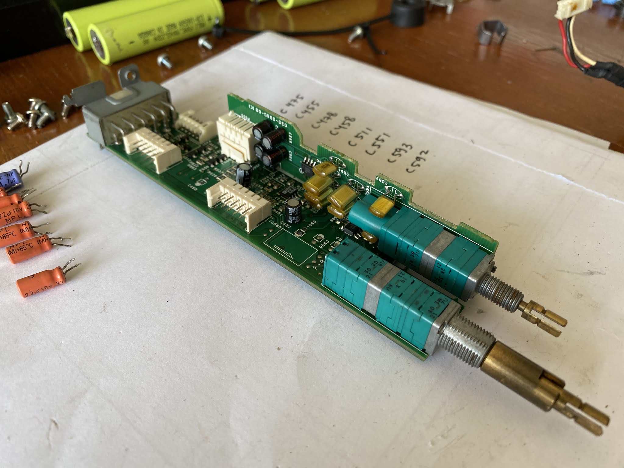
As I inspect the capacitors replaced is all in the pre-amp section. All capacitor are for the signal capacitor. So I orders few Elna Silmic II capacitors, they are 4 pieces 22uF and 2 pieces 3,3uF. Originally this Clarion DRX9255EXL is a car audio source that provided 4 channel line output. It is common for a car audio system using front and rear speakers. But for home stereo, I will only using the front output for 2 channel system. The reason for that, I will remove the unnecessary cable from the back panel of this unit.
To start with, I must first disassembly this unit into pieces. I start with remove the bottom panel and front panel. This is also the right time to clean all up.
I thought I should remove the front and side panel but later I think this is unnecessary.
First things first, those ugly capacitors should remove immediately.
I inspect the PCB trace and make sure I only put the new capacitor for the front output only.
And this is the result, all new capacitor are all in.
Before I put all parts together, I think this unit need a little bit clean up especially for the dirty front panel.
Now, it looks like new.
Looking to the back panel of this unit, this is what it looks right now. It is more simple after I removed the BUS connector and the antenna cables.
One more information about the others connectors, there is a round connector besides the main power socket. This connector is Clarion proprietary optical input. This is what I will use for the digital SPDIF input later on.
I will make separate post about how to modify this unit to accept the digital SPDIF signal and become an external DAC.
To looks more cleaner, I remove all unnecessary cable from the main power socket.
The ACC red cable which needed to connect to the power 12 volt in order to makes this unit operate is also removed. In substitute for that, I shortcut the ACC pin and the Power pin inside the main board. Same function but cleaner look.
The 6 pins socket that connect to external DC-DC converter is the starting point to insert the sleeve. I remove those pins one by one and then put the sleeve in.
The DC-DC converter I got here is not a very good looking unit. I spotted several broken PCB trace inside and I did some repair on it. I also did several capacitors upgrade especially in the power filter capacitor that degrading over time especially for car audio application like this.
This DC-DC converter case is ugly to look at. I better painted it black for better appearance.
As you can see the yellow and black cables from this DC-DC converter is the only cables connect to the external 12 volt DC power supply.
I can use any switching power supply adaptor, like what I am using here is taken from the old Sharp LCD TV. The power supply output is 12 volt 5 ampere which works fine.
For the lower noise power supply, I can use 12 volt battery.
This it's for all restoration and capacitor upgrade.
This is what the unit looks right now. You notice I also painted the top cover black so it is looks like a new unit.
Because this unit is now a home audio CD player, so I attach the bottom chassis with the rubber feet.
After spending many hours to make the unit like this, how is the improvement to the sound quality?
I could tell besides it has better appearance right now, the sound quality are improve so much. Those Elna Silmic capacitors makes the sound smoother and less edgy, although previously the sound is already good.
I really satisfy with this unit so far. I listen all my music albums again and again and I can tell that no music are bad if they are playing with this multibit R2R DAC. Perhaps the reason for bad music is because the audio system is bad enough that cannot translate the emotion from the music to the listener.
Disclaimer: Any statement and photos in this article are not allowed to copy or publish without written permission from the writer. Any injury or loss from following tips in this article is not under writer responsibility.


Good afternoon. The scheme is located at: http://sova-audio.blogspot.com/2015/02/spdif.html?m=1
ReplyDeletePhotos are not displayed in the blog. Could you update them? Without your photos, I have no understanding of how and what to solder. I apologize for the Google translator.