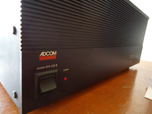
This Adcom GFA-555 II on the table here is second hand but in very good condition. The previous owner using this amp for years and then keep it under the table for long period of time until dust covered all of this amp. The photo bellow actually the amp after I clean it up. I have tested it to play some music and find that the small transistors on top board near the input RCA are all too hot.

Perhaps the adjustable pot has changed during cleaning, so proper bias setting is needed here. This method has been describe in the Adcom service manual and you can find it quite easy by browsing on Google.
First things you will notice that the pot located on R119 for one channel and the other one is on the other side. That are the only pot to adjust the bias.

Before put the multi-meter test pin, please make sure that this amp is not connect to anything else, such as: input source or speakers. Only power cable are connected to the mains outlet. You will find the pin near the main transistor. Each channel has 2 pin, each on every row of the power transistors. This is one of the pin I mentioned.

The pin are noticeable, so you will spot them easily. Use the volt meter to do this adjustment. Then this is the other pin for the opposite side.

Set the volt meter then turn on the power amp. I am very surprised for the first bias measurement read about 78 mV, too high compare to the recommendation is only 10 mV.

Back to the pot and trim until achieve the proper level. Each pot are set for each channel.

With deviation about +/- 1 mv, the 11 mV is an ideal value of the bias. This bias should re-check again after the amp idle for about 10 - 20 minutes.

This is the others channel tested with the same result after idle about 20 minutes.

That's it! This is very simple and easy adjustment for this mighty amp Adcom GFA-555 II.
Disclaimer: Any statement and photos in this article are not allowed to copy or publish without written permission from the writer. Any injury or loss from following tips in this article is not under writer responsibility.
Thanks a lot, very helpful !!
ReplyDeleteEasiest to.measure across the resistor legs (use a clamping lead) and measure 16mv. Comsult your manual for technique.
ReplyDelete