Building TDA1541A DAC is very simple compare when I built the R2R PCM56P DAC here. This is because TDA1541A is a stereo DAC in single IC package. The input TDA1541A is I2S that can be pair easily with the popular PCM2706 USB to I2S module.
My previous portable size TDA1541A USB DAC & headphones amplifier here is successfully brings the music enjoyment in the small size. Of course there are some cutting corner especially in the regulator power supply section to make all components fit in that small casing.
This is my second built TDA1541A USB DAC, but right now it is the desktop size DAC. I have this nice and elegance thick aluminum casing for quite a long time but not sure what suitable project for it until this project come. So lets begin.
Early Disclaimer: Please don't follow the schematic in this post yet since the sound quality result doesn't come as my expectation. There will be the part 2 of this DAC built here.
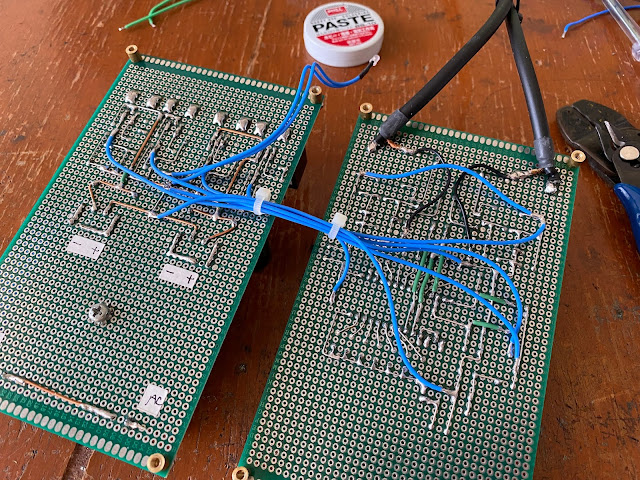
The concept of this DAC is using 2 simple PCB board inside the casing. One PCB for the power supply section and the other for the DAC section. The overall casing dimension is about 21 cm x 21 cm with the plate thickness 6 mm.
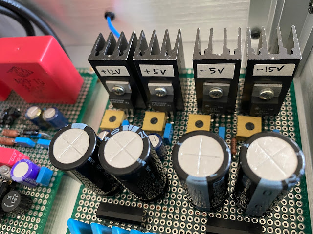
The power supply board is using 14 VA Talema transformer. The secondary output is dual 18 volt then fully rectifier by 2 bridge diodes. I also using 2 pair adjustable regulators IC for precise output voltage. It is 317 and 337 regulator IC.
The next board is DAC section. This TDA1541A using 470nF for all DEM capacitors. I also using and Sanyo OS-Con capacitors for each voltage input near the IC.
The difference with this USB DAC built is on the analog section. While previously I am using op-amps, then in this built I am using single FET per channel same as Lampizator FET project that he shared on here. When I read it, I really curious how this simple schematic with a FET can sound like using a vacuum tube. In this project I using Philips BF245A and follow based on the original Lukas Fikus schematic.
But before I describe this FET sound output quality, let me share my work for the casing first.
Once it is all finished, this internal DAC is really beautiful to look at.
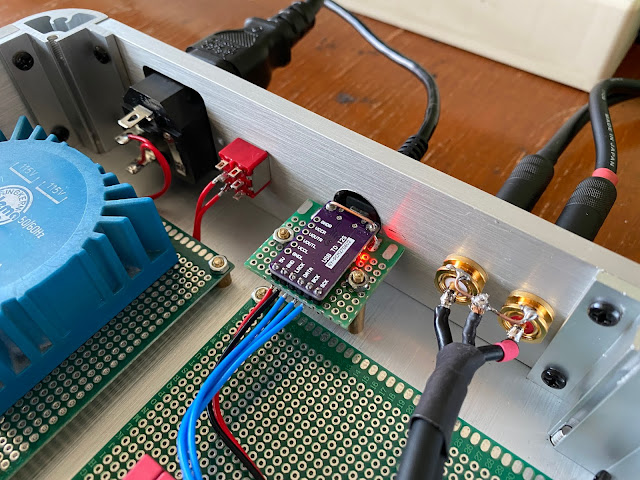
The last steps is just connecting the power supply board to the DAC board and also the input output terminals including the PCM2706 USB to I2S module.
My initial test for this DAC is sound dry. Moreover the sound output is distorted especially for some music that recorded with higher gain output. I listen to music that have suitable gain with this DAC for a while and this is not quite impress me so much.
The main problem for this distortion is might be the gate input for the FET is higher than the FET can handle. So after several trial, this is the modified schematic for far better result.
The IV resistor is 50 ohm using 2 pieces 100 ohm Dale RN60 in parallel.
The FET gate input resistor is rise to 2K2. I using Holco H4 resistor. The quality of this resistor really give significant impact to the sound quality, especially lowering the noise.
I adjust the voltage input at this analog stage up to 13.6 volt, this is to reach the 11.4 volt measured at the FET drain pin.
The 820 ohm from the FET source to the ground is using Vishay 1K and Holco H4 4K7 in parallel. you can use single 820 ohm resistor as well.
The output capacitor is 3.3uF WIMA MKP10. Higher than the original schematic using 2.2uF.
The sound quality is so much improve with this slightly modification from the original schematic. You see from the photo bellow, I did test the parallel resistors value and evaluate the impact to the sound.
My sound impression with this DAC is the FET at analog section really coloring the sound just like using vacuum tube at the output. Note should be taken that the analog signal output from this FET is only about 1 volt or less. This is very small number and I should crank up the volume control from the amplifier much higher than the normal listening using the others DAC.
So I let this DAC just like this and start to evaluate the sound quality first.
Disclaimer: Any statement and photos in this article are not allowed to copy or publish without written permission from the writer. Any injury or loss from following tips in this article is not under writer responsibility.


No comments:
Post a Comment