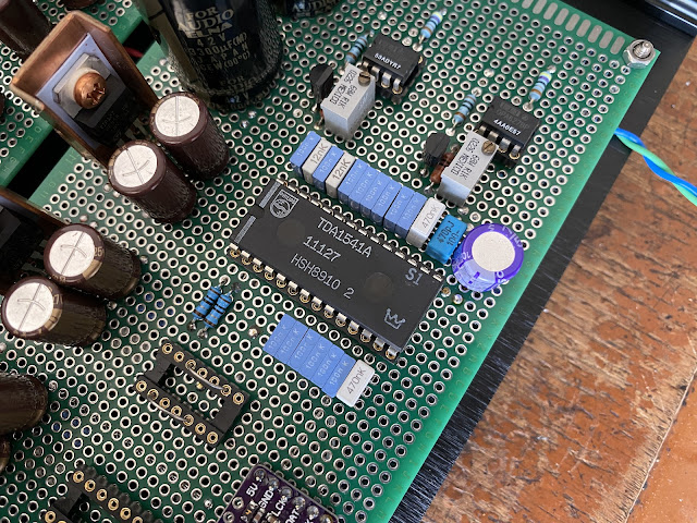
This year, I built again a TDA1541 DAC. This is because I still have one DAC IC spare, together with the others parts required.
The main difference is the power supply circuit is now using simple discrete Darlington transistor with Zener diode as reference voltage.
In this post, I will share the finishing build process, continue from the previous post.
I also will compare to listen the music with or without the asynchronous circuit.
Let's take a deep dive.
To begin with, I take some time to check the voltage output on each power supply circuit. This discrete power supply requires more attention because the number of voltage drop are different when it under load or when it idle. I don't want the voltage too low, or worsen too high. So, the Zener diodes are change many times until I got the suitable voltage for the DAC components.
Once I can confirm the voltage are within the manufacturer specification, I can start wrap all accessories together.
I still have a TDA1541A S1 single crown attached on my old Nakamichi DAC-101. So, I take the IC out and install it to the new home.
At this point, the asynchronous circuit is bypass and I make an adjustment to null the DC voltage at the output. One channel can be null, become zero DC offset, but the other channel still appears 150 mV DC output. This still not safe for any DC amplifier that will connect to it.
The only amplifier I am confident to test this DAC is the Elekit TU-8900 amplifier. It is 300B tube amplifier, and by its nature, the capacitor and output transformer on it act as DC coupling. This amplifier review will be shortly appeared on my next post:)
With the asynchronous circuit bypass, how does it sound?
I can say simply wonderful.
The vocal is like human voice. The bass is punchy and the overall musicality is amazing.
This is perfect sound!
Now, I try to using the asynchronous circuit.
Before I jump to the conclusion, what is asynchronous circuit anyway?
This basic circuit is using dual positive edge triggered D-type flip-flops IC. I am using 74ACT74 because it can work up to 100 MHz clock frequency. The "T" on the ACT meaning it receive TTL format coming from the oscillator module.
The incoming digital signal that flow through this asynchronous circuit is only WS and BCK. For the DATA signal is directly pass through to the TDA1541 DAC IC. The incoming signal WS and BCK are triggering the flip-flops and taken the signal from the oscillator to the output and feed to the TDA1541 DAC IC. This process improvement will depend on how clean and precise the oscillator module attaches to it.
The oscillator components is independent module that encapsuled with steel case to avoid RF interference. The main specification for this oscillator is how much the error appears on each second or in ppm. I am using 50 MHz as minimum oscillator frequency for this circuit and the ppm number is 100, which is not great. So, I bear in mind for the result.
The sound result with this asynchronous circuit is not my cup of tea. I can hear the magic human voice is disappears compare when this circuit is bypassed. The musicality also have a degradation, it seems like it add more noise, not such hiss or hum noise, but the sound is like not accurate.
I listen several tracks and not to giving up with the result, I change the oscillator with higher clock frequency, is the 80 MHz oscillator. The result is in my opinion is better, more refine to the music just like when it plays without it.
So, do I need to keep this circuit on? Or I better bypass it anyway?
I cannot conclude yet, but at this moment, I still enjoying the music with this TDA1541 DAC.
Disclaimer: Any statement and photos in this article are not allowed to copy or publish without written permission from the writer. Any injury or loss from following tips in this article is not under writer responsibility.


Asus STX II on PCM1796 + Sparks Lab operational amplifiers. this bundle has changed the attitude towards delta sigma. Before that, 1541 was my favorite
ReplyDeleteSome type of Delta sigma DAC also perform really well. For the TDA1541 DAC is one of a kind. Not the best in my opinion, but it is special.
Delete