It is been awhile I am using Parasound DAC-1000 and satisfy with the sound. Moreover, my amplifier is also Parasound and enjoy this combo a lot. But when I look again to my DAC collection and try to find what left from my DIY journey within few years back, I don't have much. They mostly gone already, sold to my friends and fellow that appreciate my built. Their feedback for the sound quality gives me an excitement.
So, since few months back, I started to build another DAC again, from what left in my components bin. With my spares time that already limited, consume by my main professional work, this DAC build is slow.
So, let's share this DAC build.

This TDA1541 DAC build is straight forward. I think nothing new for the DAC circuit. It is non-oversampling TDA1541 that using PCM2706 as USB to I2s converter.
Of course, there always a different in every of my build.
The main difference is now using discrete power supply regulator, not using integrated circuit like fixed-regulator or LM317/337. As many would aware that those IC voltage regulators produce high frequency noise, just like switching power-supply. This noise is not good for DAC application.
In this DAC build, the discrete power supply schematic is not complex. It is a Darlington transistor using TIP122/127 with resistor to Zener diode as voltage reference. This conventional regulator is good against the voltage ripple, and make it multiple steps can reduce the ripple even more.


The power transformer in this DAC is using Bando sealed transformer, taken from the old CD player. The secondary output are 10-0-10 volt and 14-0-14 volt, suitable for this TDA1541 DAC application.
Using this high-quality transformer is one of my main recipes for good sounding DAC.

For the enclosure, I am using ready built casing bought from China. It is all aluminum with high precision-built quality. I measure the components that I need to place into this chassis, then I drill few holes and mount them on it.


The next things is the DAC board.
This DAC board also have the second stage of discrete power supply section. This for extra ripple reduction.
The other difference in this DAC build is the high-frequency asynchronous digital filter section using 50 MHz, low ppm oscillator and a flip-flop IC 74ACT74.
The TDA1541 by nature will always have DC at the analog output. So, at the analog stages, I put DC-servo to null the output to zero. This is to avoid using capacitor output that mostly colorized the sound.


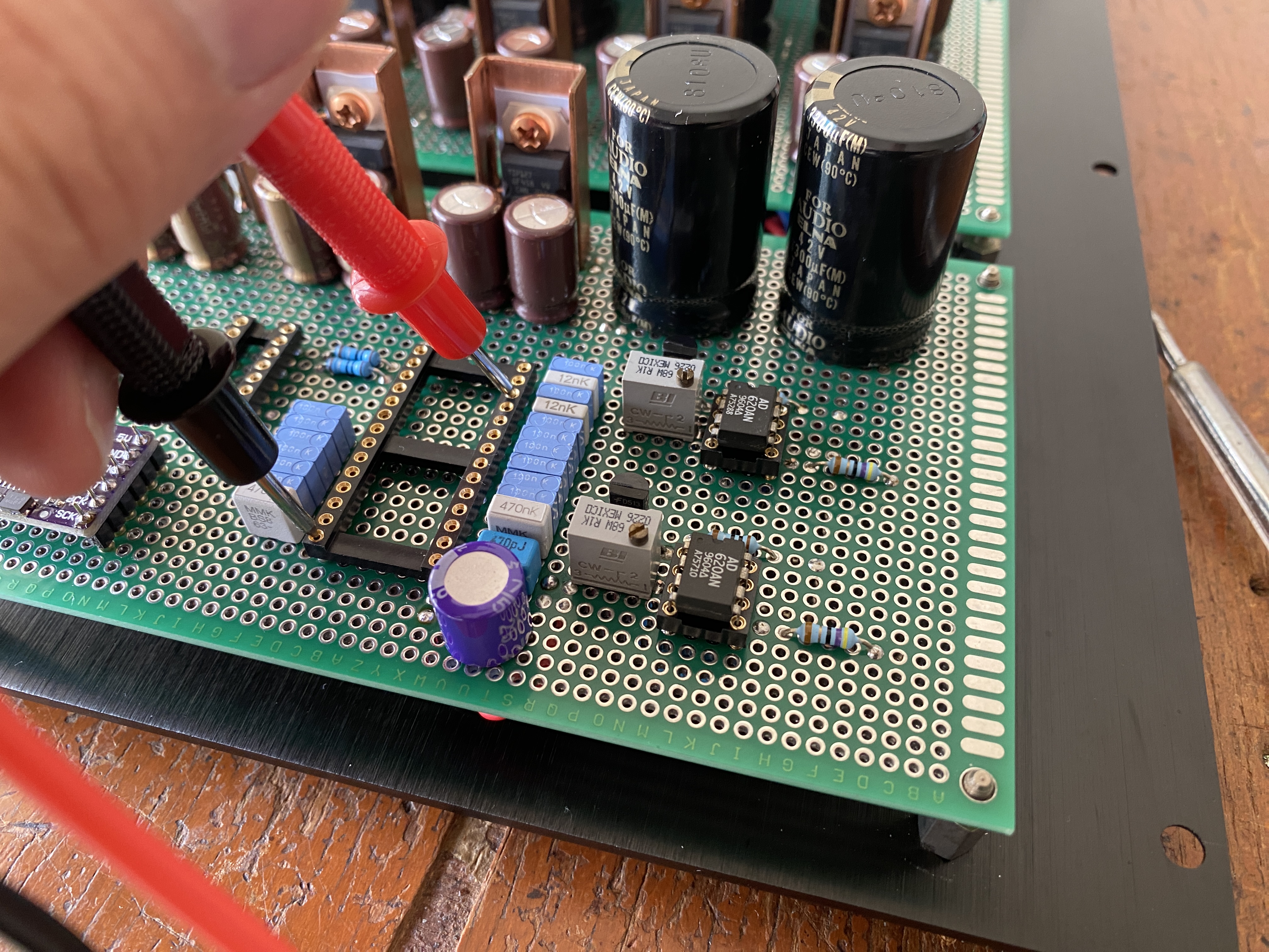
This DAC build to about 90% complete.
The rest of the steps are measuring the voltage, set the IC's, null the voltage output, and finishing the layout, which will also consume a lot of time.
Honestly, at this state, I love the looking of this DAC.


I will post the result later on, after this DAC completely finished and tested.
Until then, see you.

Disclaimer: Any statement and photos in this article are not allowed to copy or publish without written permission from the writer. Any injury or loss from following tips in this article is not under writer responsibility.
Keren om..selalu rapi 👍🏾👍🏾
ReplyDeleteTerima kasih 🙏
Delete